Lightweight Printable Composite Structures
Abstract
This proposal lays out the trajectory of research based
around the fabrication of light-weight structures formulated from a composite
of plastic and fabric. The work proposes to build upon the current vein of
research in extruded plastics to create a viable method of construction
utilizing this method of fabrication.
Context
There have been several project in recent years at various
academic institutions such as SCI-Arc, MIT, and the University of Michigan that
have sought to explore the possibilities and properties of CNC extruded
martials. This research builds on the ideas inherent to 3D printing
technologies and seeks to both scale up and explore a variety of material
possibilities such as plastics and concrete. Most of these projects have been
facilitated through a process of attaching either a repurposed industrial
plastic extruder or a custom designed extruder to a multi-axis robotic arm.
The projects can be divided in to two categories: first
expanding 3D printing technologies, and second, exploring the properties of
extrusion. The first category of projects deals with the direct translation of
digital three-dimensional forms into physical manifestations. The second deals with the affect of processes
extrusion and attempting to push the extents of the physical properties of the
material. None of these projects, however, work with this technique and
material as an actual building material.
Previous Exploration
Fabric tests and selection
During the fall semester of 2012 at the University of
Michigan, in collaboration with Jake Newsum, experiments with this material and
technique were begun. This method encompasses several crucial elements. This
project entails printing extruded plastic on fabric to create lightweight
structural panels.
Fabrics
The first element of this technique is reliant on the fabric
selection. A variety of fabrics were tested including an assortment of natural
materials and synthetic. The finding was that the plastic didn’t bond with the
fabric. Synthetic fabrics had better success on some of the selections. It was
found that on polyesters tend to fuse with the Copolymer Polypropylene used in
the extrusion. Other fabrics such as
rip-stop didn’t fuse at all. The conclusion is that fabrics of similar plastic
composition as plastic fuses the best.
Plastic Printing Techniques
As with all the extrusion projects, the process relies
heavily on two elements: the first is temperature and something that has been
termed “smash”, or vertical offset. The temperature dictates the strength of
the fusion with the fabric; it was found that the greater the temperature the
greater the bond. However, an excessive temperature could also cause too much
penetration with the fabric, resulting in bonding with the substrate material
and ultimately in some undesirable bonding and staining. The ideal temperature
range was determined to be between 180 and 210 degrees Fahrenheit.
The second element, the vertical offset, determines the
structural rigidity as well as cohesiveness of fabric accumulation. Two
techniques were discovered, is to print above fabric, the second is the print
with a determined offset less than the height of the printed plastic in
successive layers, inducing “smash”. The ideal offset was found to be about 1/32 of
an inch. This technique, although the more structural of the two, causes a
limited amount of distortion due to drag and pinching of the fabric.
Structure
The structure of the panels is determined based on size of
the panels. This in turn determines the techniques necessary. Smaller panels,
roughly 12 by 12 inches can be made structural with a single line profile of
plastic. However it was found that smashing plastic provides better shear resistance.
A second technique developed was filleting the corners, this proved to be more
successful than printing diagonals across the panels. The most successful
structural solution, however, was a combination of these techniques. A single
layer of smashed plastic directly on the fabric provided shear resistance while
a layer of plastic with a larger offset directly on top of this provided a
structural cross section. Adding a fillet to this allowed for panels of
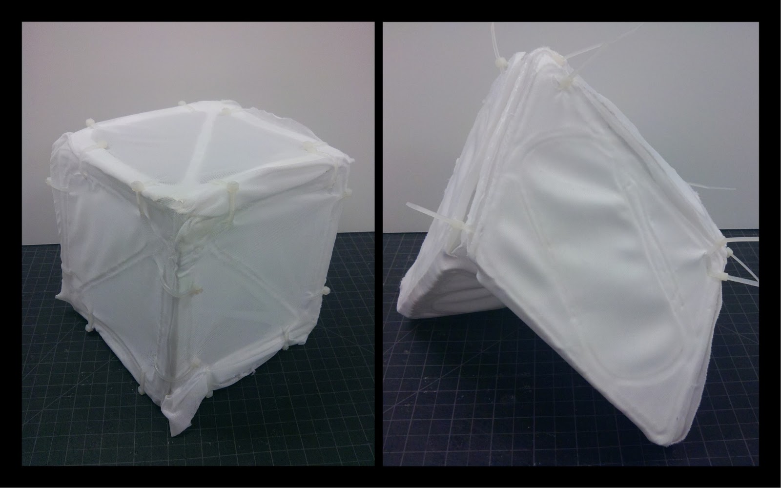
significant strength. One structural
test of a 6 inch by 6 inch box, earlier in the process tested at over fifty
times its own weight.
3D Assemblies
The difficulty this technique was discovered in assembling
the panels in to folded geometric prisms. The method has resolution issues
resulting in warping and infidelity of panel assembly. Connection tests focused
primarily on attaching contained geometric volumes into an aggregated assembly.
Attachment methods utilized consisted primarily of internal sowing and a
pull-string method, which would ideally allow for minimal expression of the
connections. However, further testing will be required to both improved the
fidelity of the printing process as well as alternate connection methods.
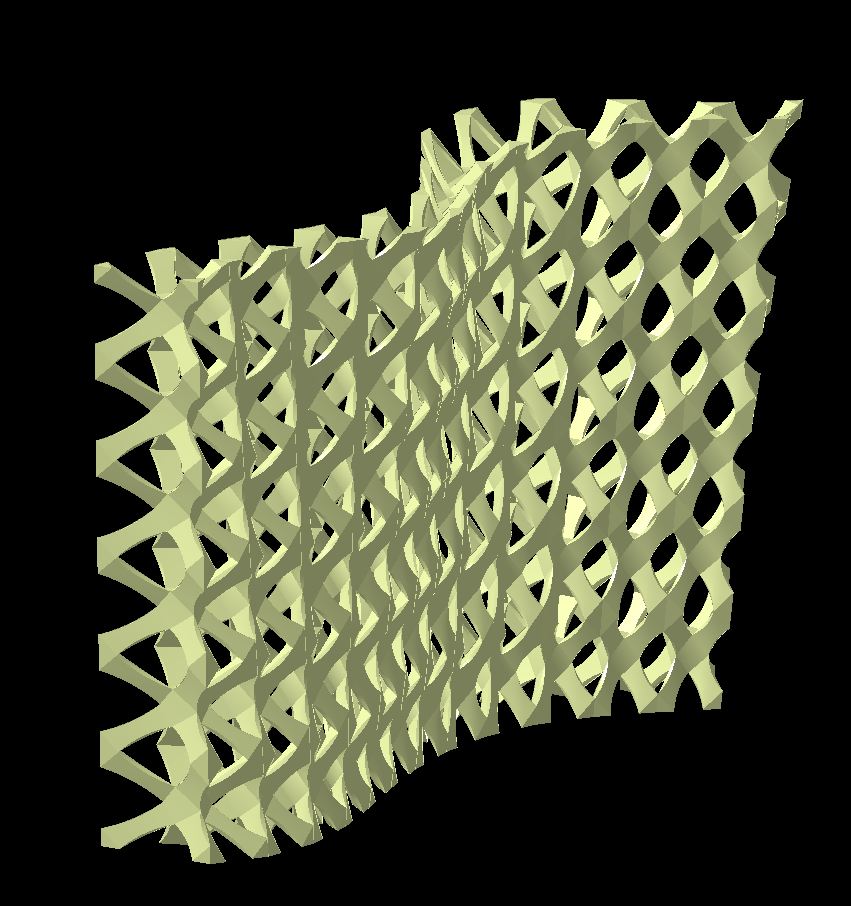
Composite
One of the more significant discoveries during this process
was the behavioral qualities of the plastic fabric fusion. By altering and
varying the tool paths to result in open geometries rather than profile lines,
it was discovered that the assemblies behaved more as a composite. The fabric
provided flexibility and tensile restraint while the plastic provided rigidity
and stiffness. Depending on the tool path arrangement, most of these composites
took on spring like characteristics.
Light Weight Structures
The success of this project is in the ability to create
structural components without the use of fixtures or precut fabric patterns.
Proposal Project
This semester the work is proposed to be continued and a
variety of methods to build upon the calibration of last semester. While
developing methods to improve the techniques and fidelity of the current
methods, further exploration of the possibilities of this technique will be
explored.
3d Panels
While the previous semester’s panels were limited to flat,
two dimensional prints, this semester, explorations into three dimensional
panels will be conducted. Two potential methods are apparent: the first is
pressing the printing the plastic on loose fabric stretched on a frame, using
the pressure of the extruder nozzle. The second is to stretch the fabric over a
three dimensional forms.
Robotics
Another opportunity that is quickly apparent is the
incorporation of robotics. Taking advantage of the open fabric surfaces at the
center of the panels to create apertures is the first of these opportunities
and the second is taking advantage of the light weight qualities of the panels
to create dynamic surfaces.
Composite
The alternate and or parallel priority is to further the
explorations of the properties of the composite. This will encompass most of
the same issues as the development of the panels. But will also include
calibration of the dynamic qualities.
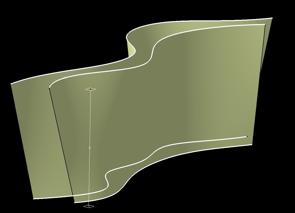
Measure of Deformation and Simulation
The calibration of these qualities will require the
cataloging of the taxonomy of the spring qualities associated with
differentiating tool paths. Once this is accomplished these properties could
then potentially be simulated allowing for incorporation into further design
opportunities.
Secondary Material Interfacing and Self-Structuring Solutions
Both of these opportunities require further exploration of
structural solutions. The first is to develop methods of interfacing with other
materials such as wood or metal structural systems. The second solution is to
continue to explorations of self-structuring methods utilizing plastic and
fabric.
Fidelity
All of these explorations require further exploration in
improvement of the fidelity of the printed tool paths. One of the first steps
is to explore improved methods of securing the fabric to reduce the drag. The
use of magnets has potential. The second avenue of improvement is to explore
increased control of the plastic extrusion.
One of the first apparent solutions is to experiment with alternate
nozzle systems for the extruder. Decreasing the diameter of the nozzle and
experimenting with forming the hot plastic as it is extruded will be the first
of the explorations.
Final Demonstration Project
The culmination of this experimentation would be presented
as situational design situated on a yet to be selected site. The sited project
will take on the form of a self-structuring system possibly forming an
enclosure or pavilion.


Bibliography:
Sciarc-
MIT-
mich-
others:
Plastic netting: composite
extruder:
3d printing:


